 |
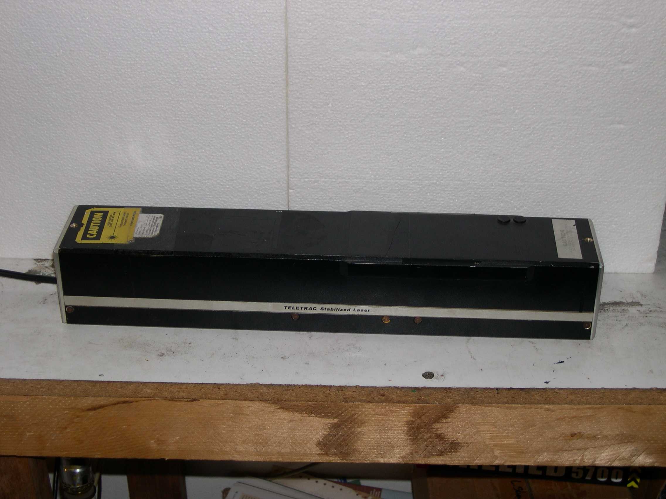
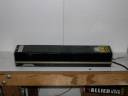
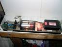
This
is the right side of the laser. The only side that has a logo. |
 |
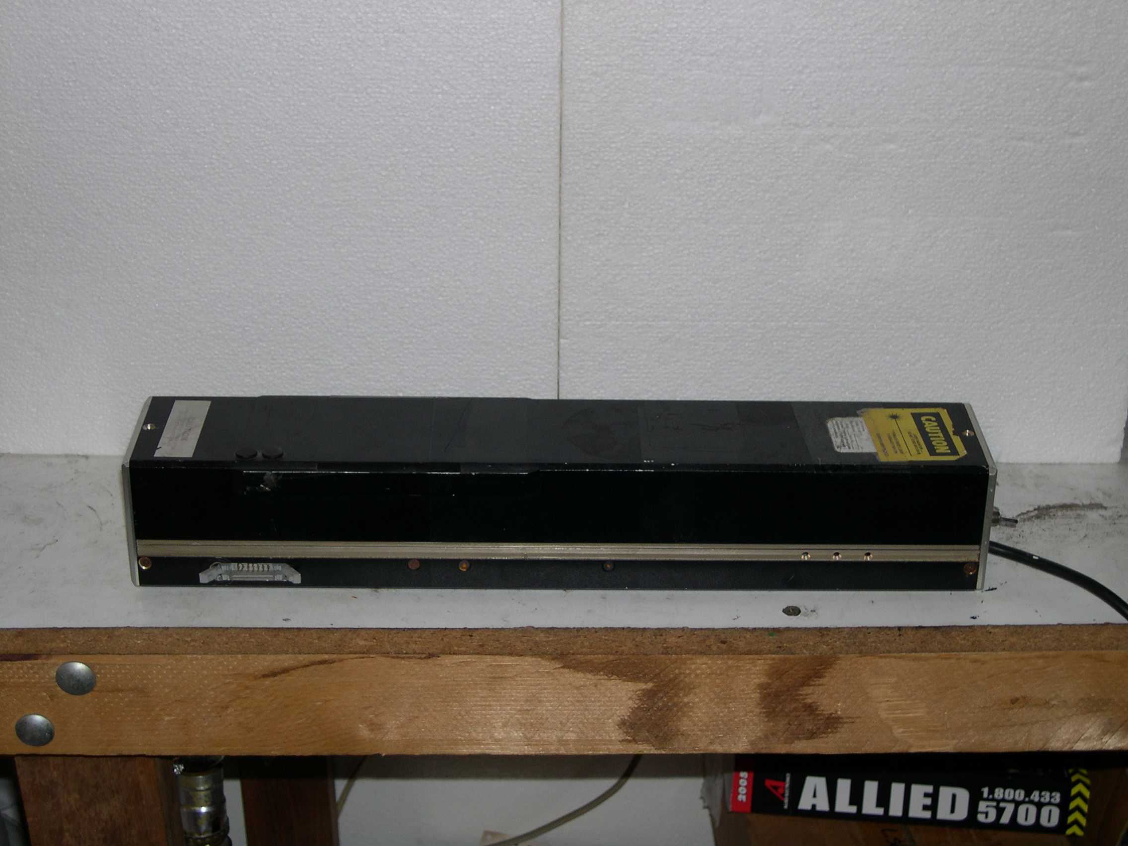
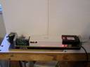
The
left side of the laser. Note towards the left the connector for the
interferometer receiver electronics. |
 |
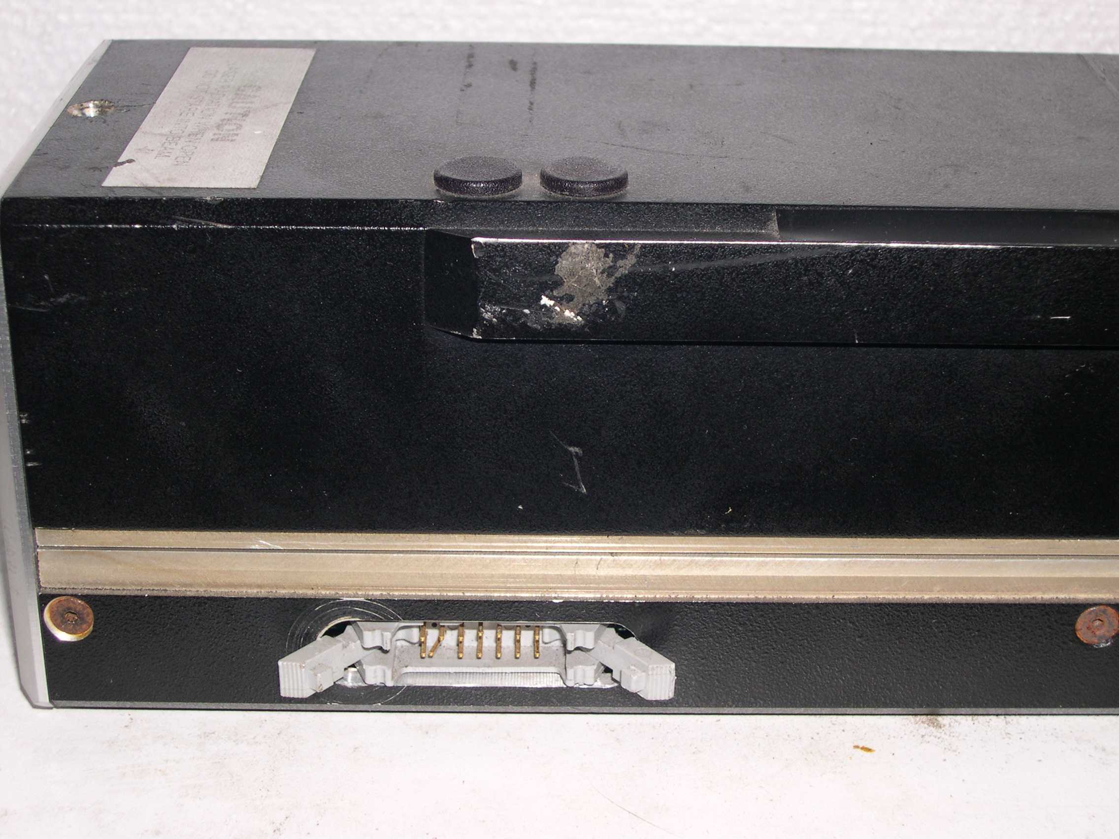
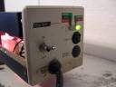
A
closeup of the interferometer electronics connector. The two little
plasic caps are pluggin holes that allow access to the sin and cosine
trimpots inside. |
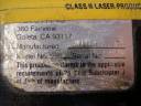 |
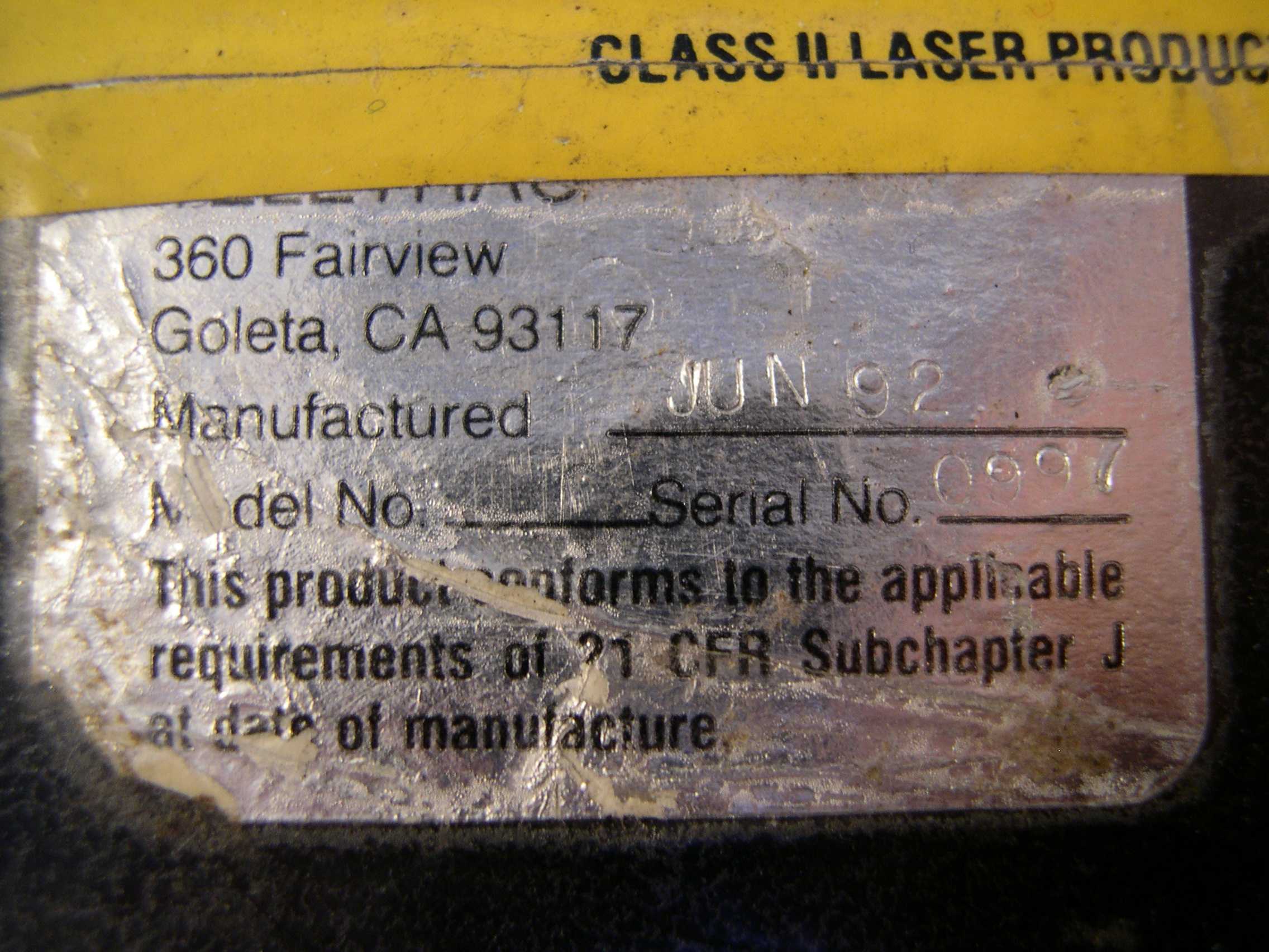
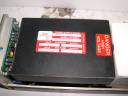
The
manufacturer's label. Made June, 1992. Serial 0897. The model number
field is blank. |
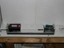 |
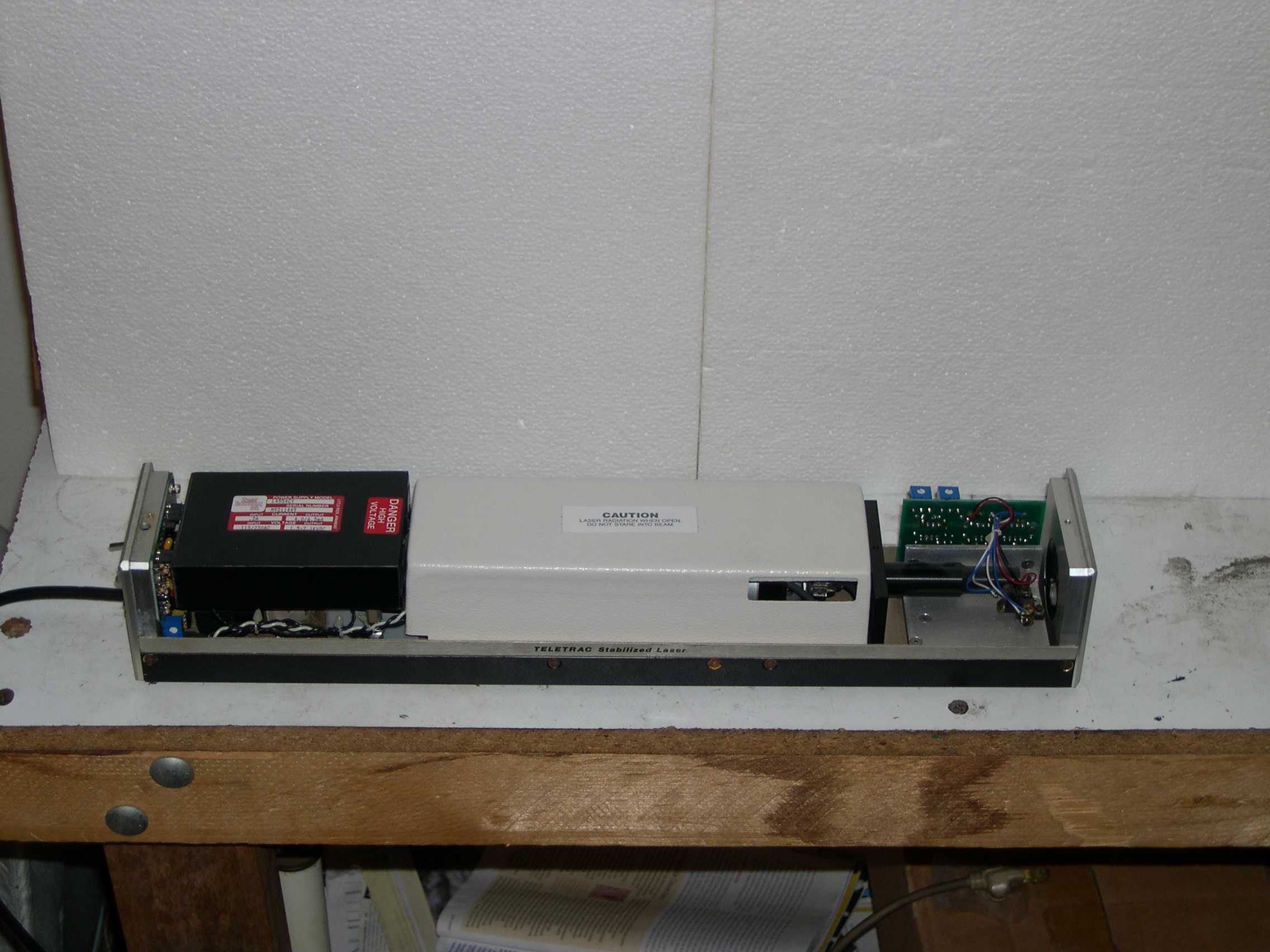
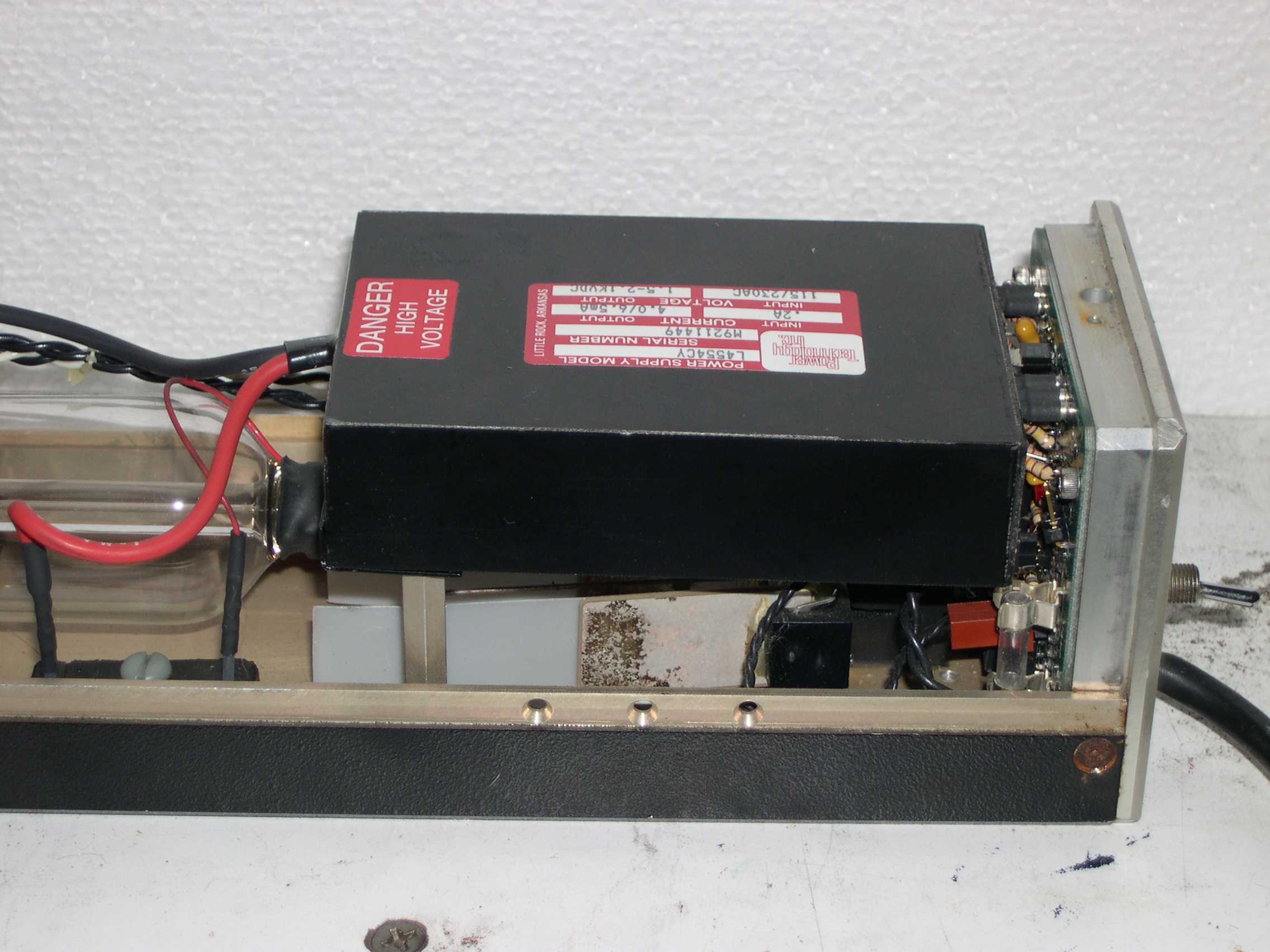
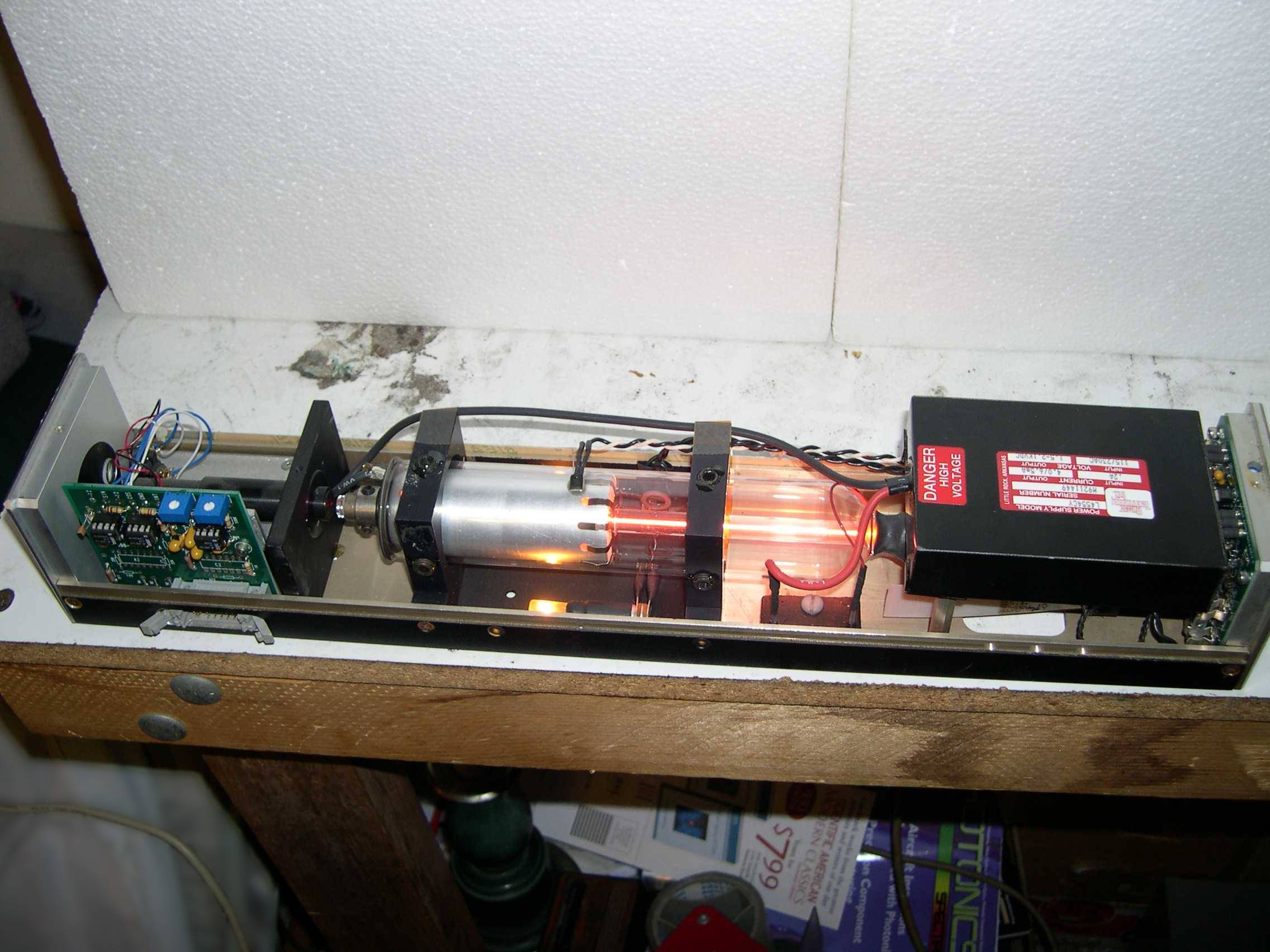
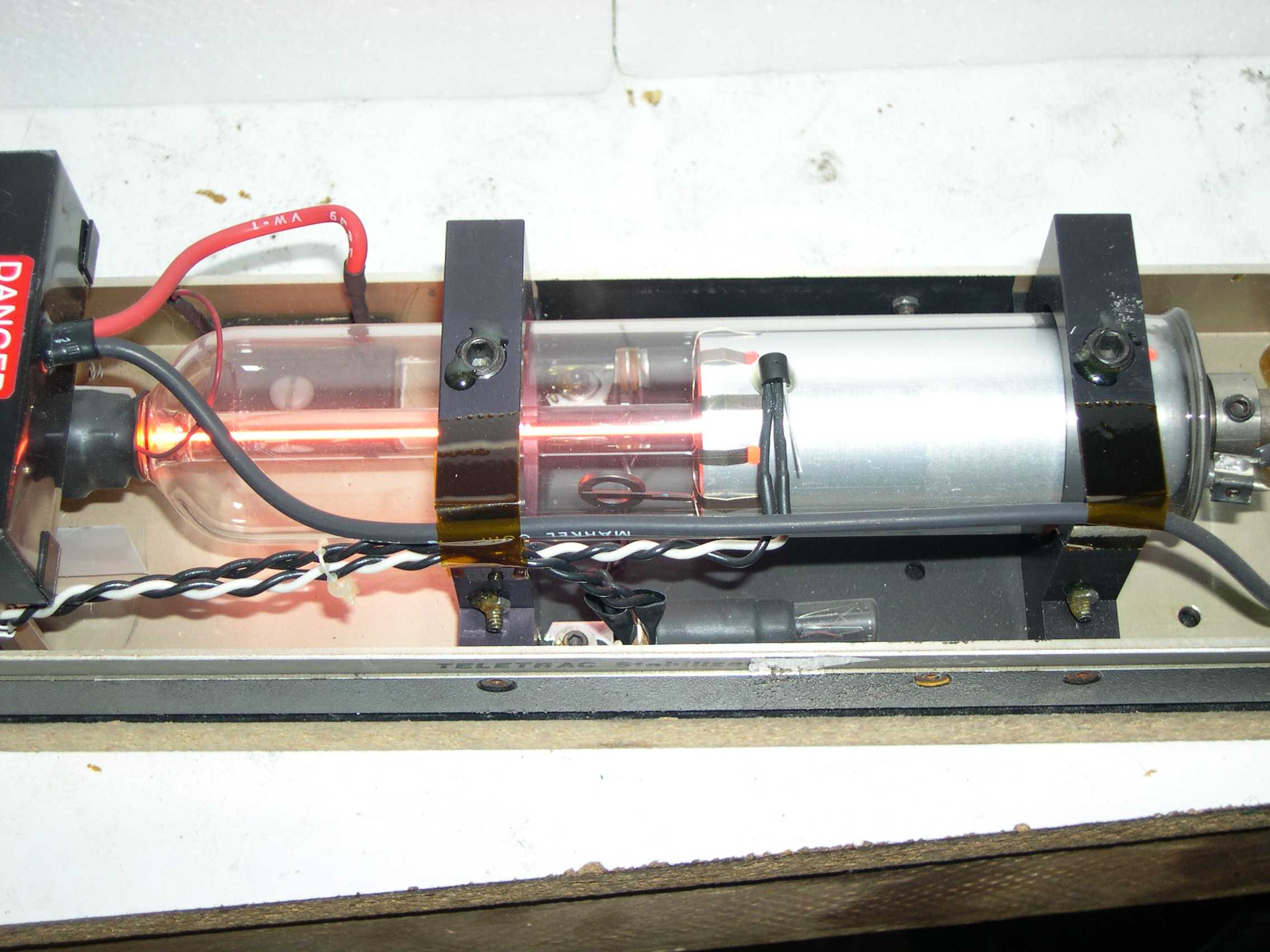
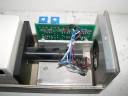
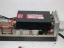
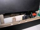
Right
side view of the laser with the main cover off. On the left is the
laser power supply 'brick' and mode control electronics. The white box
is a cover for air flow control. |
 |
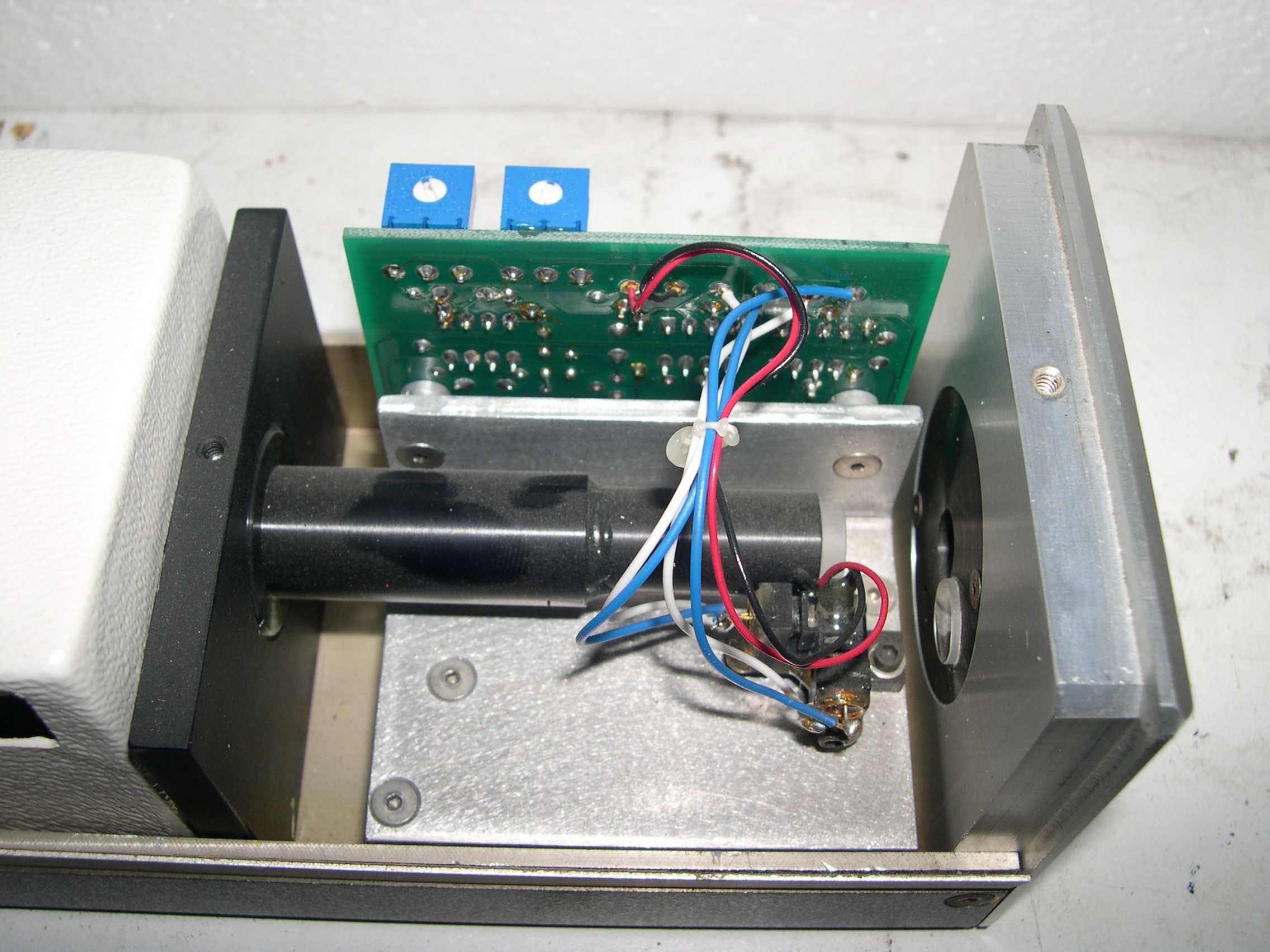
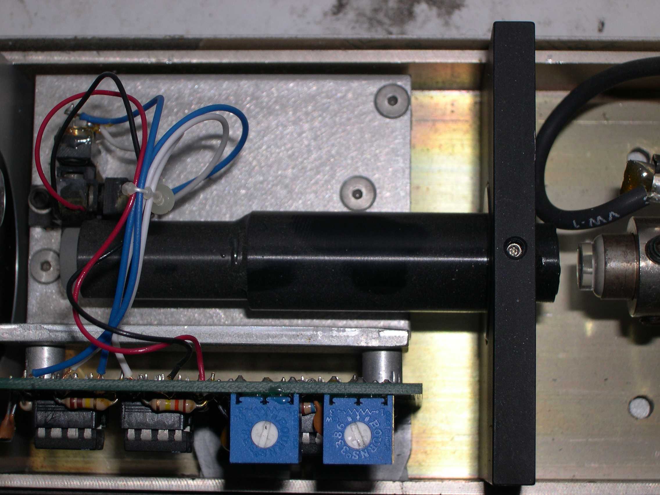
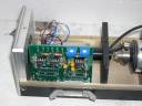
A
closeup of the front end of the laser, with collimating lens tube and
interferometer components and electronics. |
 |
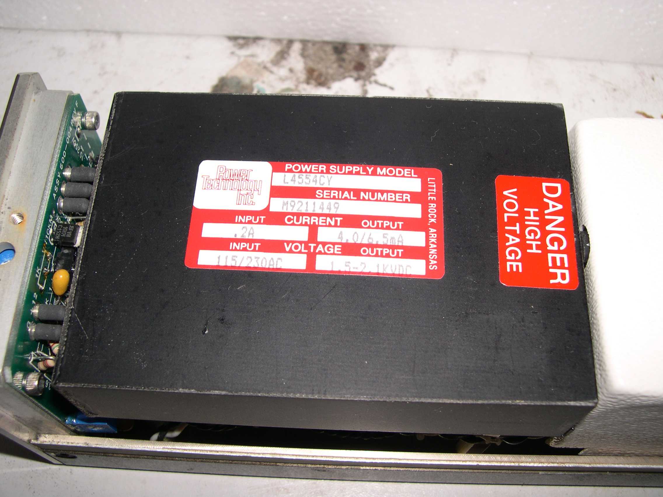
Closeup
of HeNe power supply 'brick'. Manufacturer is Power
Technology, Inc. |
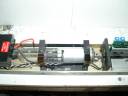 |
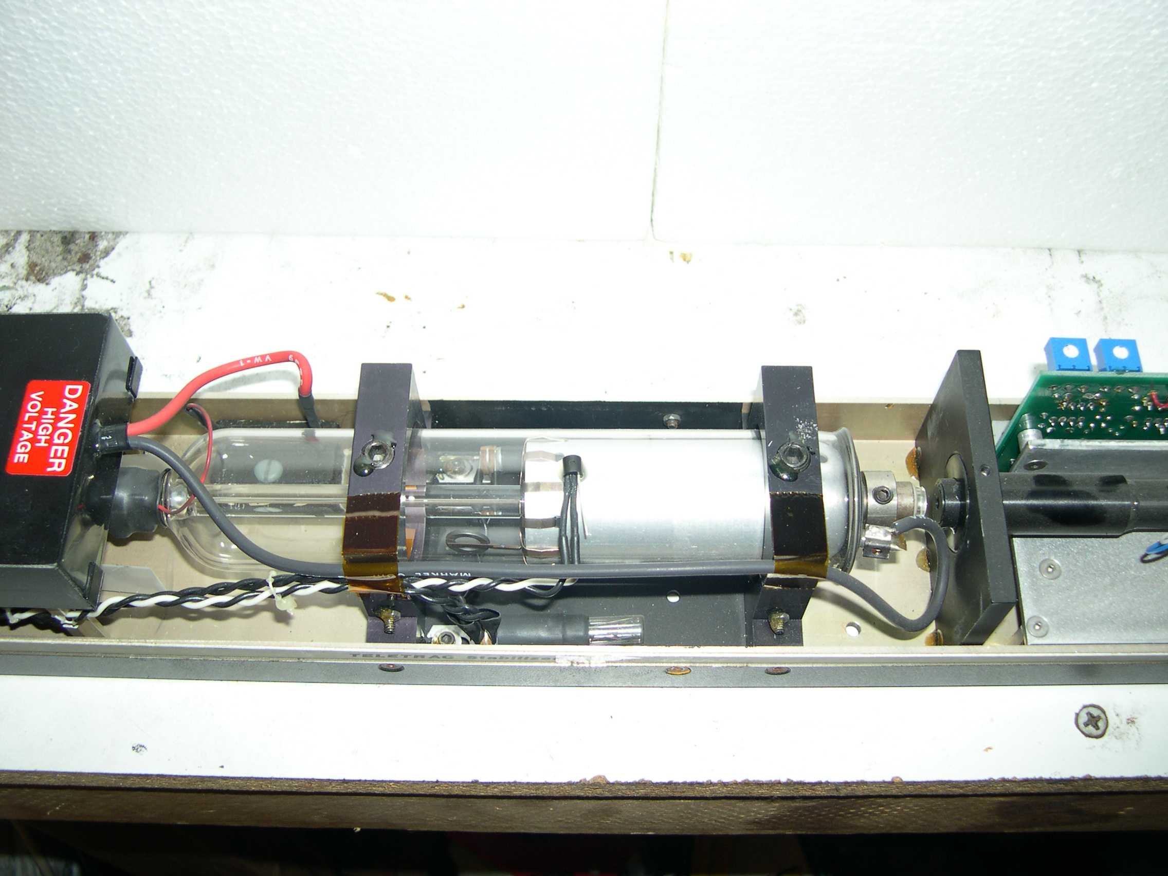
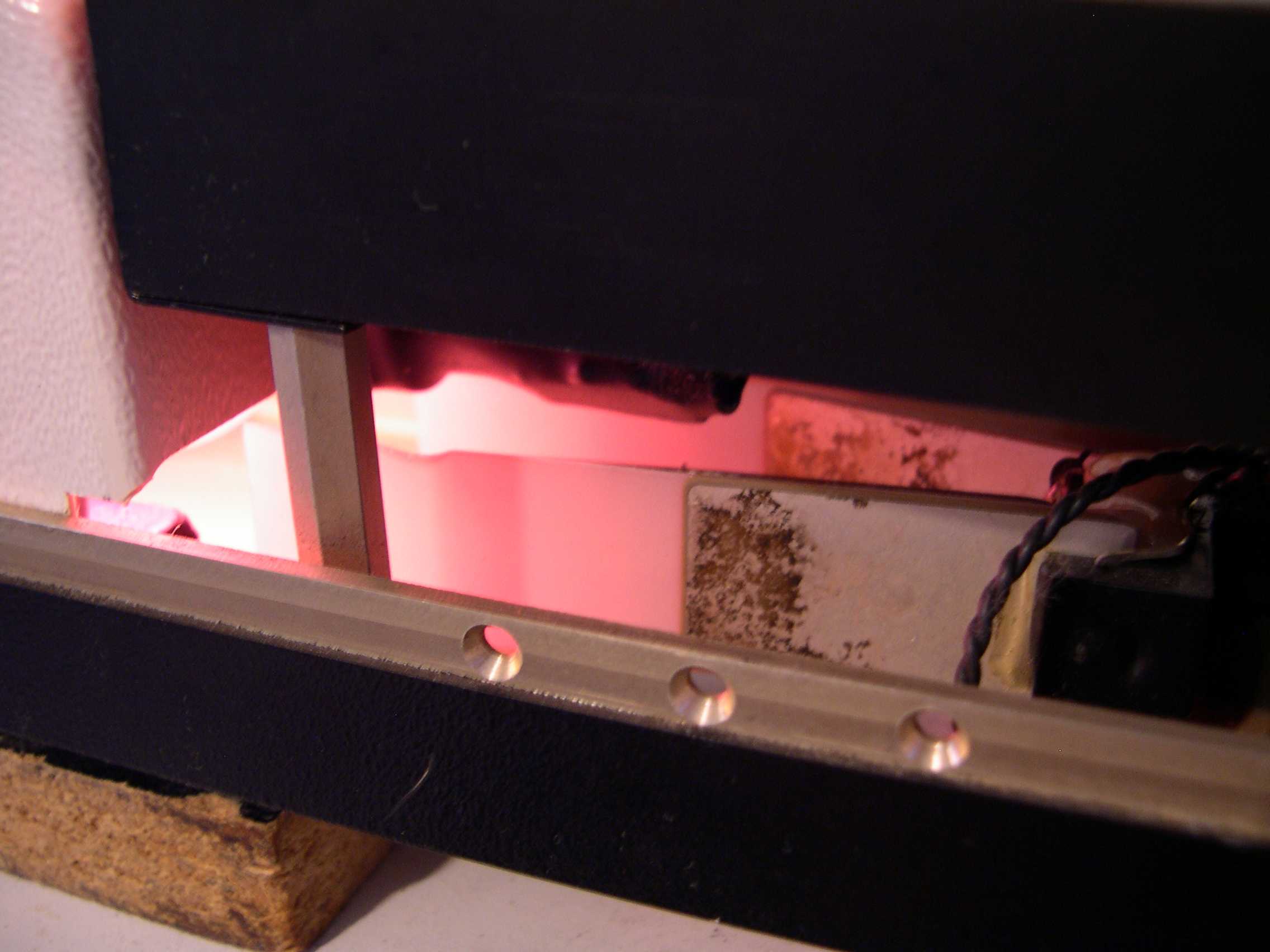
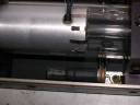
The
HeNe tube underneath the white box. Note the temperature transistor
glued to the tube and the small light bulb below the tube for adding
heat to speed up warmup. |
 |
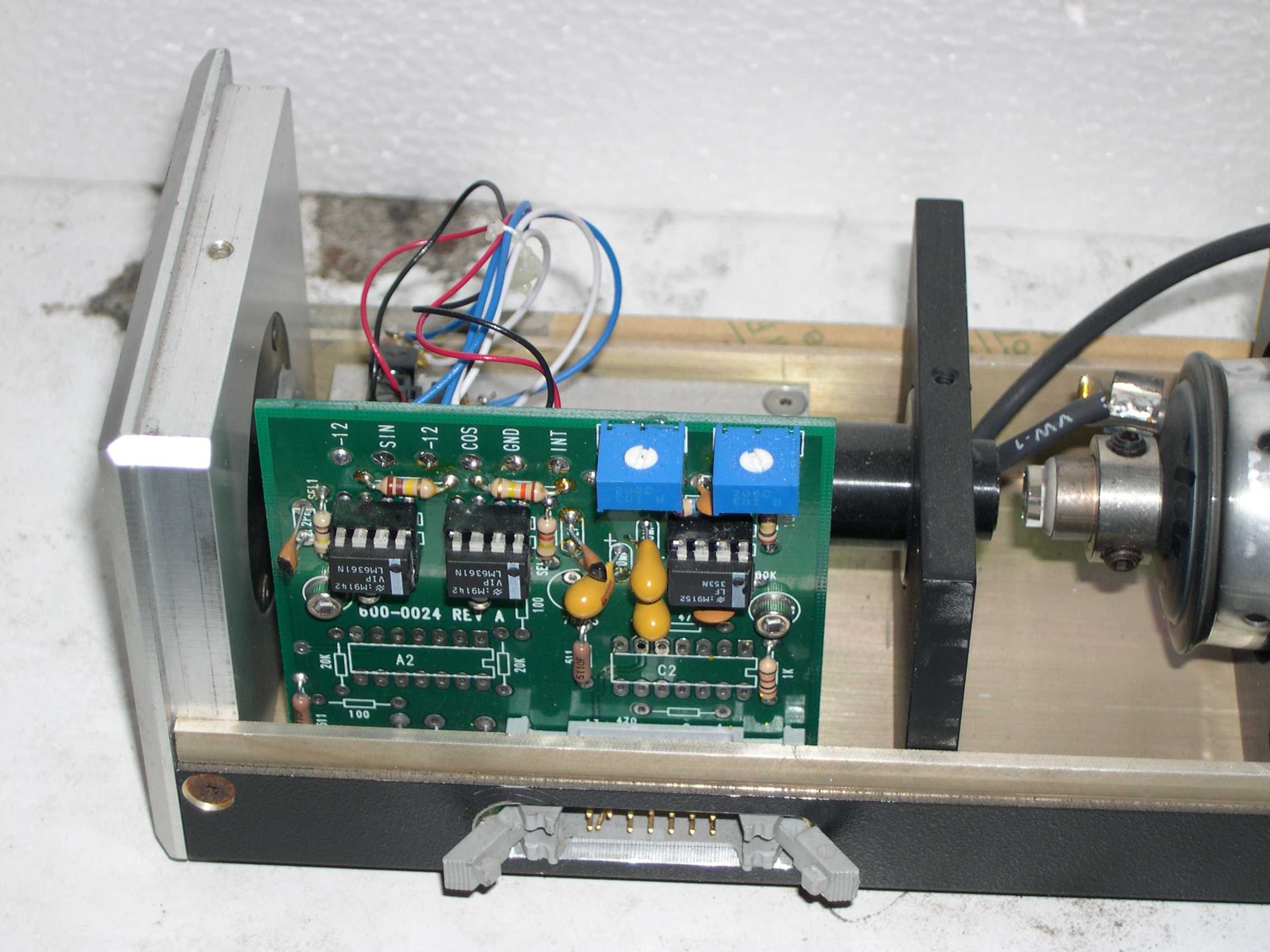
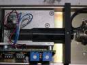
Front
end components. The PCB is the interferometer electronics. On the right
is the cathode end of the tube and the OC feeding the collimator. |
 |
Left
side of the power supply 'brick'. Below this is the piezo driven fan
blades to control temperature once mode lock is achieved. Onthe right
is the control electronics. |
 |
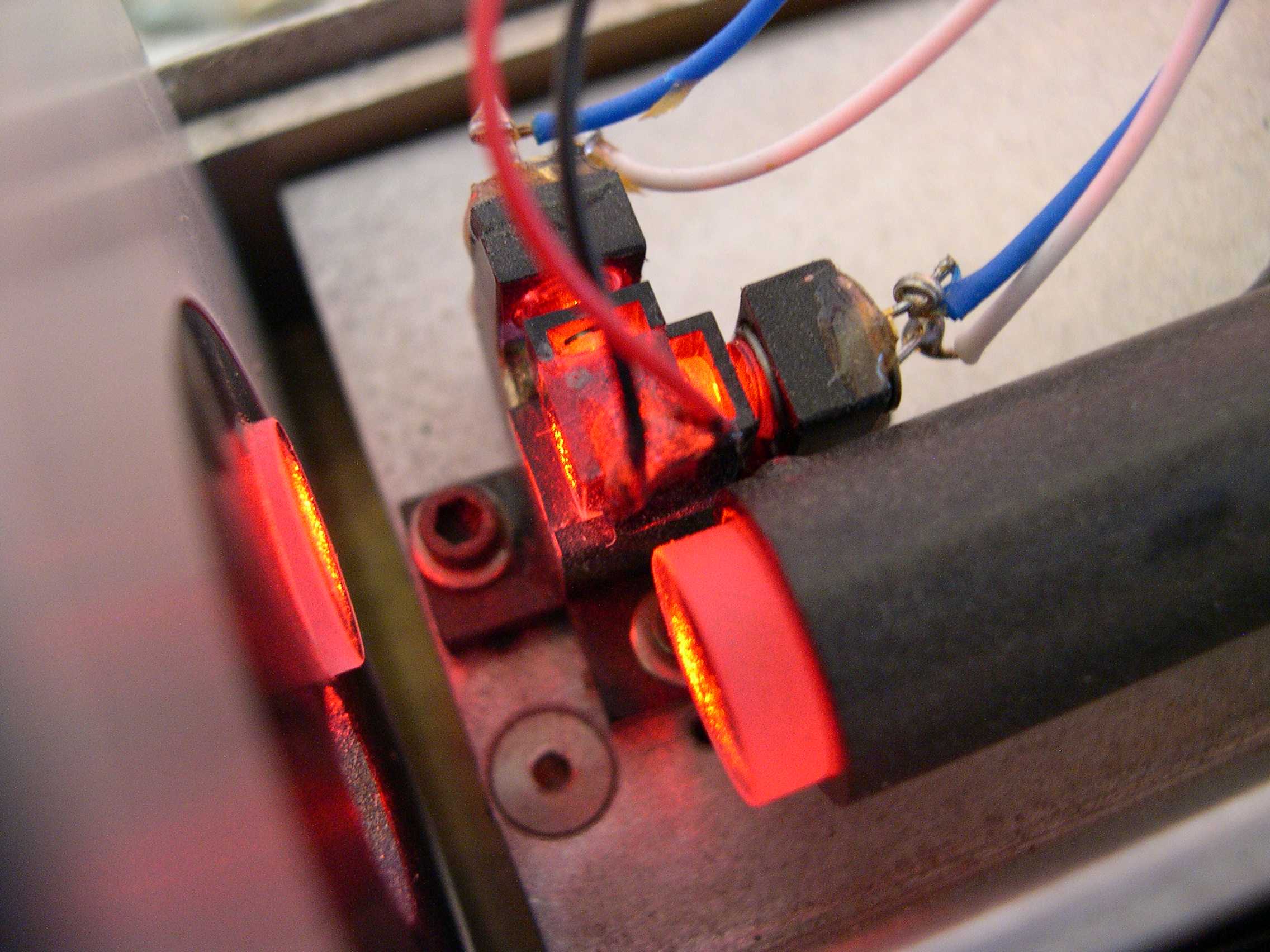
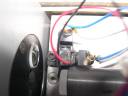
Closeup
of the tube temperature sensor (transistor) and one of the low wattage
filament heater lamps. |
 |
Closeup
of the collimator tube. |
 |
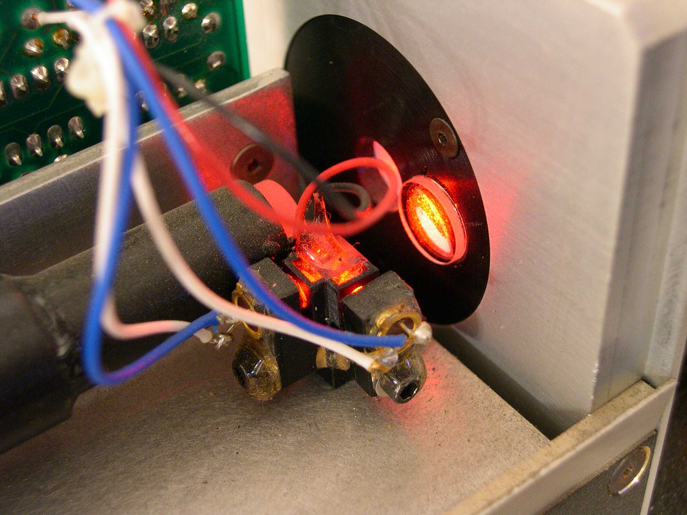
Further
closeup of the interferometer optics and detectors. The beamsplitter
cube is only 5mm!!! You can also see what appears to be either
poloarizers of HeNe line filters. |
 |
Another
view of the piezo fan. The two blades vibrate in a side-to-side motion
in opposite directions. |
 |
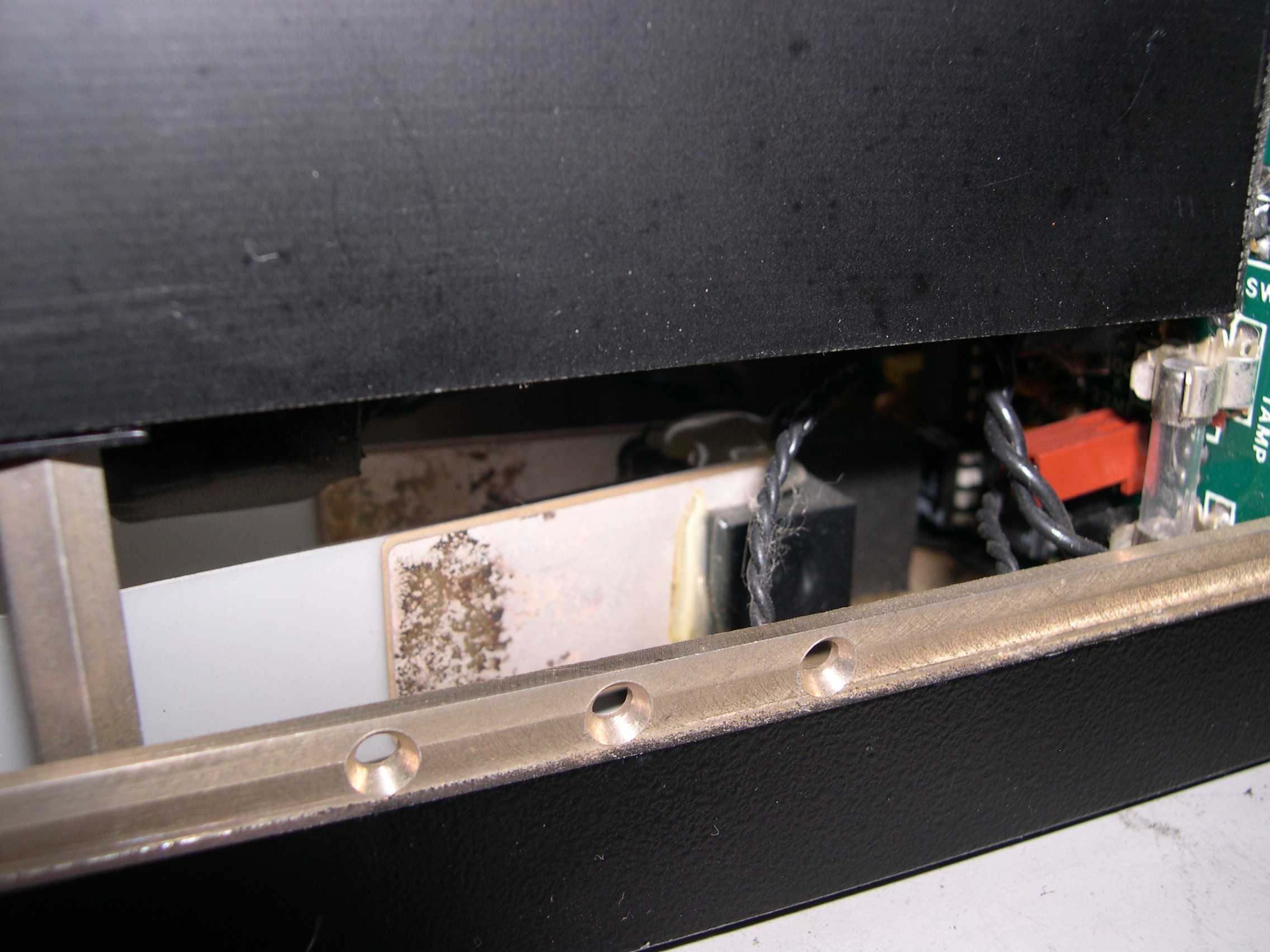
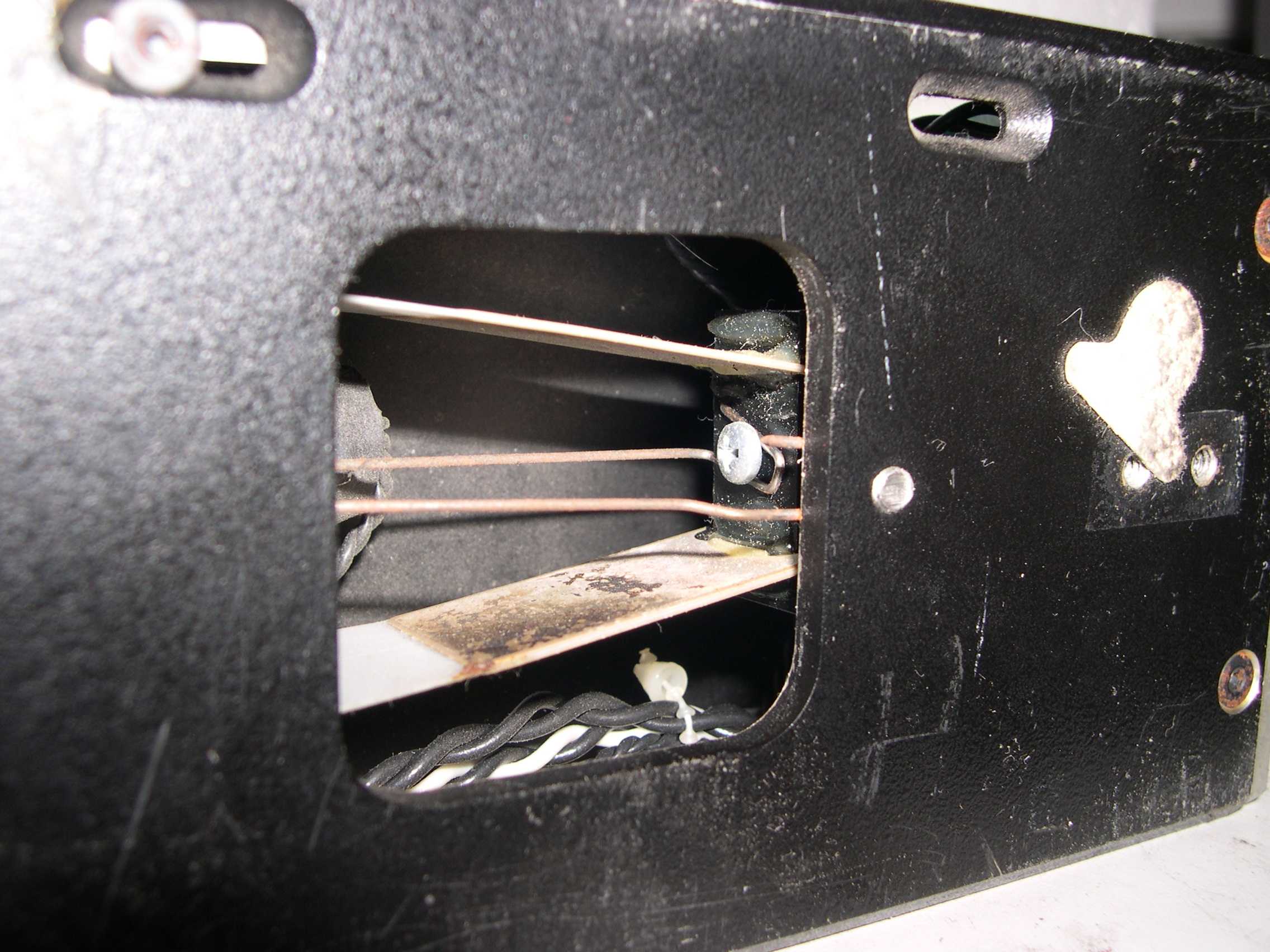
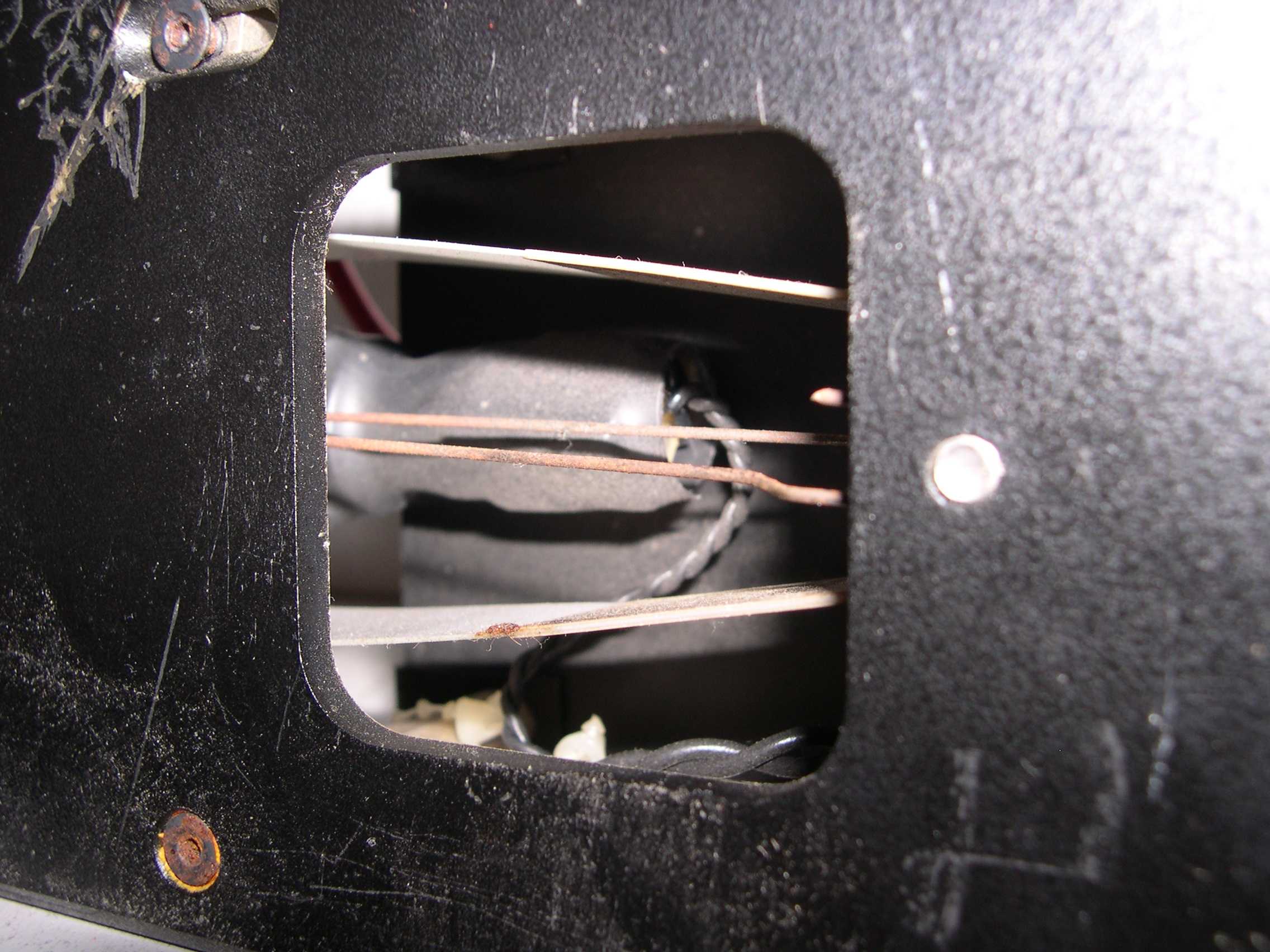
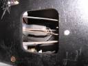
This
is the vent hole underneath the laser, looking towards the back.
Visible is the piezo fan. |
 |
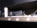
This
is the same vent hole but looking towards the front of the laser. |
 |
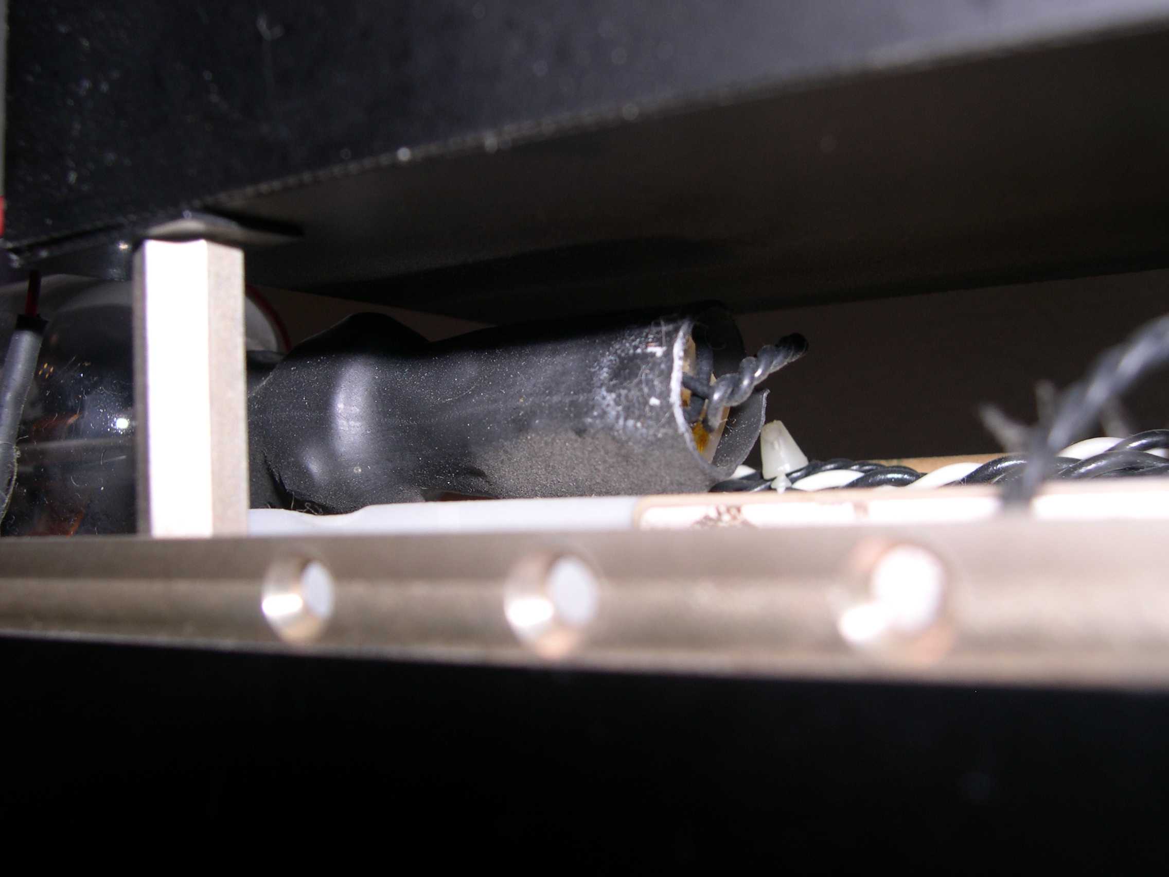
This
is a closeup of the HR end of the tube. Inside the black shrink wrap is
the detector for sensing the mode of the laser output from the HR waste
beam. |
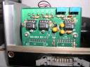 |
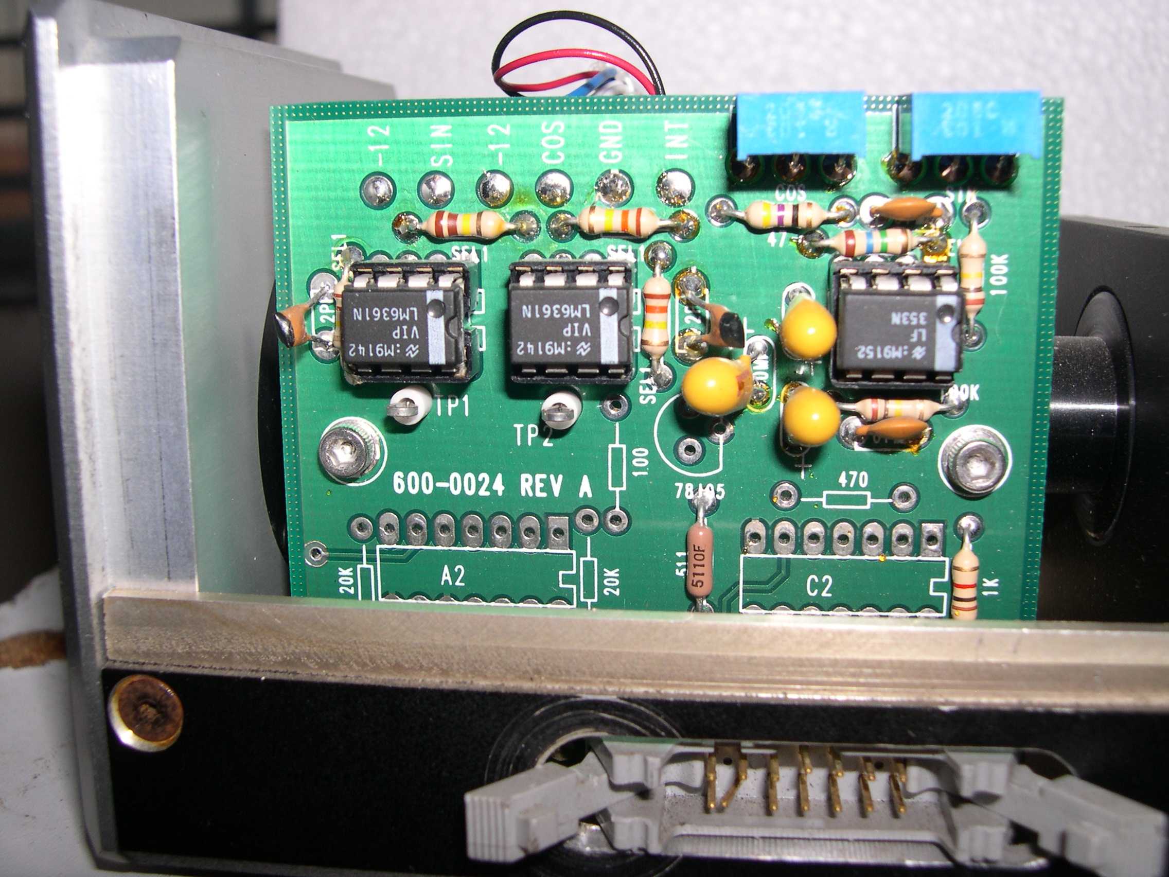
Closeup
of the interferometer receiver electronics. Very simple opamp circuits. |
 |
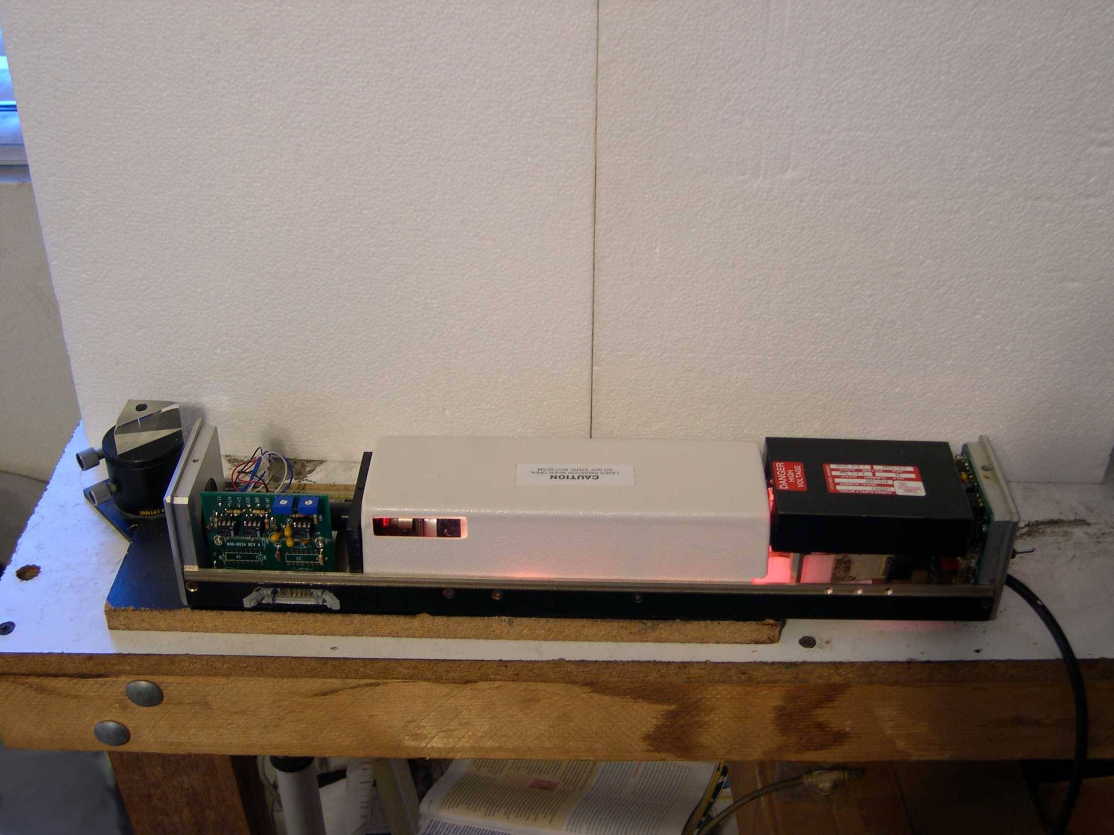
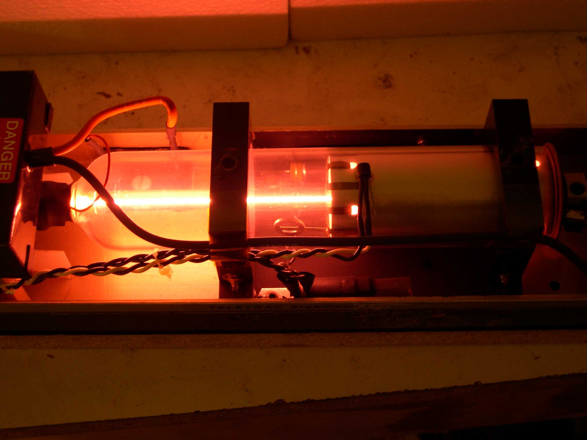
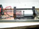
The
laser on and in warmup mode. Note the filament lamps are on. Normally
the white cover needs to be inplace to provide a controlled temperature
environment. |
 |
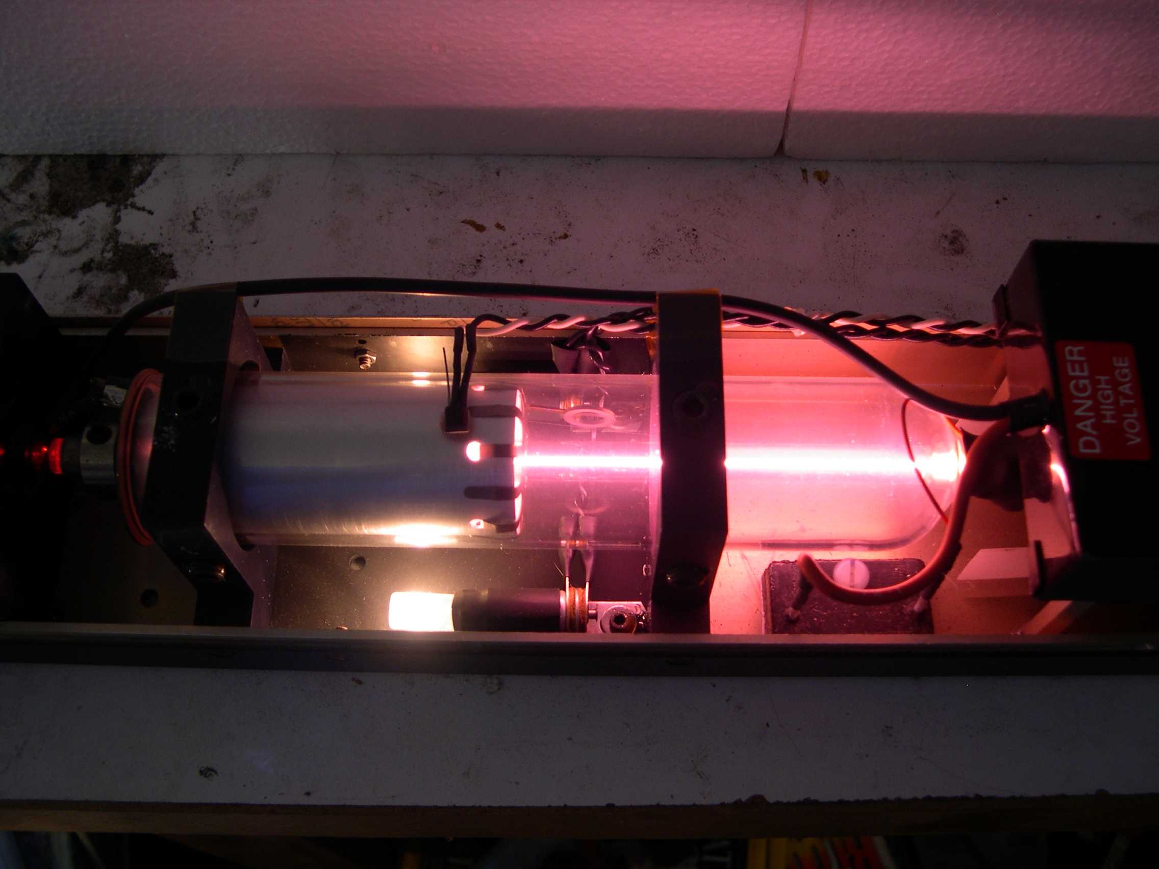
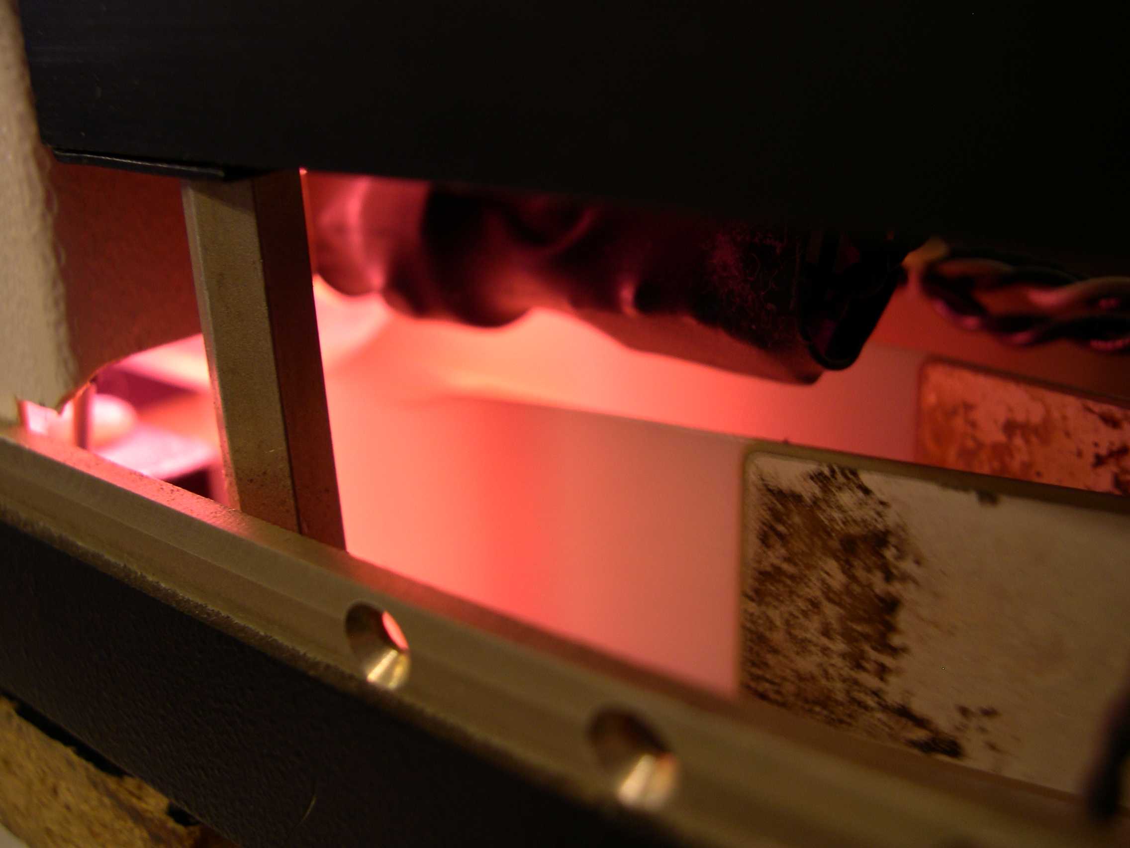
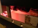
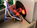
Closeup
of the lit HeNe tube while in warmup mode. Without the flash you can
really see the filament heaters and the soft salmon glow of ionized
helium and neon. |
 |
An
extreme closeup of the collimator output. I've reflected the beam back
into the interferomter optics. I need to clean those opics!!! |
 |
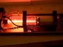
The
laser warming up with the environment cover back in place. This will
allow the laser to warm up and achieve mode lock. |
 |
Closeup
of the piezo fan blades during warmup. Once mode lock is achieved these
blades vibrate with a noticeable blur. |
 |
We
have mode lock!!! |
 |
Closeup
of the piezo fan blades vibrating. |
 |
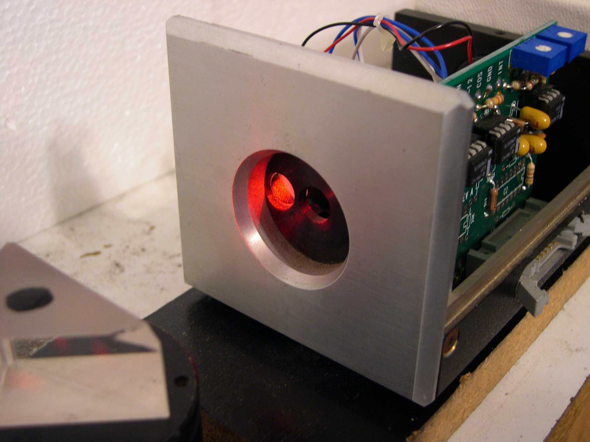
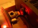
The
output of the laser is being redirected with a right angle prism back
into the interferomter optics. The laser is coming out the hole in the
center and going in the left. |
 |
Another
closeup of the interferometer optics with laser light. |
 |
The
OC end of the tube feeding the collimator. |
 |
A
view of the laser tube after warmup. Note that the filament heaters are
off. |
 |
The
same view as at left but without the flash. |
|
|
 |
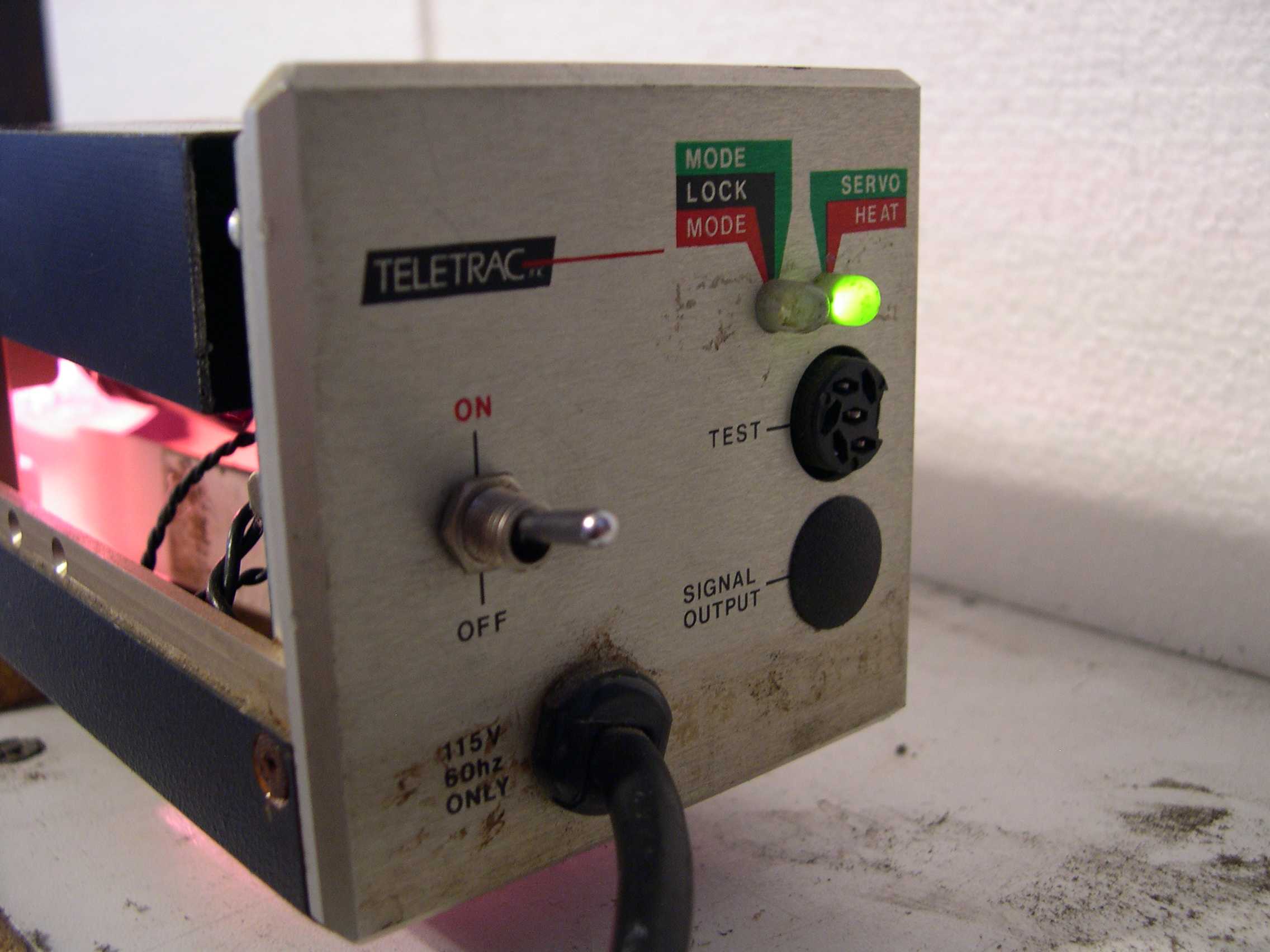
This
is a 6.6 meg quicktime MOV movie of the laser warming up and showing
the mode LED changing from red to green as the laser changes modes. |